Tuesday, 18 June 2013

Row smearing and column smearing in image

Row smearing:-Row smearing convert an input image  into a image which is smeared row wise .Here is the code ,input image and output image for the row smearing:-

for(i=0;i<height;i++)
        for(j=0;j<width;j++)
 {
if(data1[i*step+j]==0)
data2[i*step+j]=0;
else
{
for(k=0;data1[i*step+(j+k)]==255;k++);
if(k<h)
{
for(l=0;l<k;l++)
data2[i*step+(j+l)]=0;
}
j=j+(k-1);
}
}


                                                                   Input Image


Output Image


Column smearing:-Column smearing convert an input image into a image smeared column wise .Here is the code ,input image and output image for the column smearing:-


for(j=0;j<width;j++)
{
for(i=0;i<height;i++)
{
if(data1[i*step+j]==0)
{
data3[i*step+j]=0;
}
else
{
if(data1[i*step+j]==255)
{
k=0;
while(data1[(i+k)*step+j]==255)
{
k++;
if((i+k)>=height)
{
break;
}
}
if(k<v)
{
for(l=0;l<k;l++)
{
data3[((i+l)*step)+j]=0;
}
}
i=i+(k-1);
}
else
{
printf("%d",data1[(i*step)+j]);
}
}

}
}

                                                                   
                                                                    Input Image


Output Image


Monday, 10 June 2013

SURF, FREAK, BRISK, ORB classes in opencv

SURF:-SURF class is used for or extracting Speeded Up Robust Features from an image.The class SURF implements Speeded Up Robust Features descriptor Bay06 . There is fast multi-scale Hessian keypoint detector that can be used to find the keypoints (which is the default option), but the descriptors can be also computed for the user-specified keypoints. The function can be used for object tracking and localization,
image stitching etc.

FREAK:-The Class implementing the FREAK (Fast Retina Keypoint) keypoint descriptor, described in [AOV12]. The algorithm propose a novel keypoint descriptor inspired by the human visual system and more precisely the retina, coined Fast Retina Key- point (FREAK). A cascade of binary strings is computed by efficiently comparing image intensities over a retinal sampling pattern. FREAKs are in general faster to compute with lower memory load and also more robust than SIFT, SURF or BRISK. They are competitive alternatives to existing keypoints in particular for embedded applications.

BRISK:-Class implementing the BRISK keypoint detector and descriptor extractor, described in [LCS11].

ORB :-Class implementing the ORB (oriented BRIEF) keypoint detector and descriptor extractor, described in [RRKB11]. The algorithm uses FAST in pyramids to detect stable keypoints, selects the strongest features using FAST or Harris response, finds their orientation using first-order moments and computes the descriptors using BRIEF (where the coordinates of random point pairs (or k-tuples) are rotated according to the measured orientation).

Saturday, 6 April 2013

Average low pass filter for 24-bit color Image

The average low-pass filter is a algorithm where we take average of all adjacent pixels for the each pixel.We start it from the pixel [1][1] and to the pixel[h-2][w-2] and the boundary pixels copy same as available in input image.So we get a filter which takes a pixel and take average of all 8-neighbor and put it into the pixel.Thus if a pixel having a higher value than its neighbors it  is reduced thus there is only  a pass for the low value pixels and it reduces the pixels with high value.So it is called low pass filter.Here is the input and output image used for the program .There is a slight change in input and output image which very difficult to see.

Input Image

Output Image

Friday, 5 April 2013

Horizontal Flip,vertical Flip and Reflection about origin in 24-bit color Image

Horizontal Flip:-Horizontal flip is an exchange of pixels in an image which shift the image left pixels into the right of the image and right pixels in left of the image.We need to traverse the whole image column wise and put all left most pixels into the right most side .Thus we move in each row and the image we get after traversing each row is a horizontally flipped image.Here is an input and output image for the horizontal flip program:-


Input Image
Output Image
 Vertical Flip:-Vertical flip shifts the topmost pixels to the bottom most pixels thus the whole pixels from top to bottom traverse and the pixels which are at the top in the input image goes to the bottom in the output image .In this we move row wise and traverse whole image .Here is the input and output image for the blog.


Input Image
Output Image
  Reflection about origin:-In this algorithms we move pixels diagonally .Thus the pixels which are located at the top left in the input image move to the bottom right in the output image and the output image is reflection about origin .We can say that this the combination of horizontal flip and vertical flip.Here is the input image and  image for the program:-

Input Image

Output Image

Connected component labeling for 24-bit bitmap Image

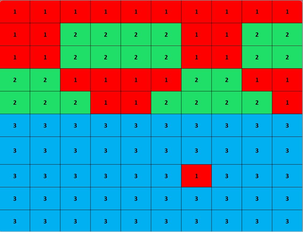
Connected component labeling is an application where we search the pixel of same pixel value and if found then labeled them with same value .Thus the whole image is processed and the pixels having same value shows the same label.This is also known as blob extraction,region labeling .Connected component labeling  is used in computer vision to detect connected region in binary digital image or color image.There is two method used for connected component labeling 4-way connectivity and 8-way connectivity .In 4-way connectivity the top,bottom ,right and left neighbors are checked while in 8-way connectivity all 8-neighbors are checked and the lowest label is given to the same neighbor .Thus the whole image is traversed and we get a labelled image.


  Here is the output of a labeled pixels of an image.We can see here the pixels with same color have same      
label.

Monday, 4 March 2013

RGB to YUV and YUV to RGB color space conversion

RGB  to YUV conversion is and YUV to RGB conversion is so simple.There are two different formulas for these two operation:-

RGB to YUV Conversion

Y  =ceil ( (0.257 * R) + (0.504 * G) + (0.098 * B) + 16)

V = ceil ((0.439 * R) - (0.368 * G) - (0.071 * B) + 128)

U = ceil(-(0.148 * R) - (0.291 * G) + (0.439 * B) + 128)

YUV to RGB Conversion

B =ceil (1.164(Y - 16)+ 2.018(U - 128))

G =ceil (1.164(Y - 16) - 0.813(V - 128) - 0.391(U - 128))

R =ceil (1.164(Y - 16) + 1.596(V - 128)) 

 Here is the input and output images for this program:


RGB to YUV Conversion:-

Input RGB Image


Output YUV Image


YUV to RGB Conversion:-


Input YUV Image


Output RGB Image


Sunday, 3 March 2013

RGB to TSL and RGB to noramalized RGB

Here we need to discuss some color space conversion which are helpful in face detection .In this program we take 24-Bit color image as an input.

RGB to TSL :- RGB to TSL conversion in which we use following formula :-


T =
\begin{cases}
\frac{1}{2\pi} \arctan{\frac{r'}{g'}} + \frac{1}{4}, & \mbox{if}~g'>0 \\
\frac{1}{2\pi} \arctan{\frac{r'}{g'}} + \frac{3}{4}, & \mbox{if}~g'<0 \\
0,                                         & \mbox{if}~g'=0 \\
\end{cases}
S = \sqrt{\frac{9}{5}\left( r'^2 + g'^2 \right)}
L = 0.299R + 0.587G + 0.114B
where:
r' = r - \tfrac{1}{3}*255
g' = g - \tfrac{1}{3}*255
r = \tfrac{R}{R+G+B}*255
g = \tfrac{G}{R+G+B}*255

Here is the input  and output image for this program:-
Input Color Image 

Output TSL Image


RGB to noramalized RGB:-In this approach the each normalized RGB channel is formed by the dividing the respective  channel with the sum of all three channel values and further multiplying it by 255.Here is the input and output image for this program:-
Input color image

Normalized RGB image